
As the restrictions in the use of Industrial Radiography (RT) has increased over the years, the need for alternative weld inspection methods and techniques such as Time of Flight Diffraction (TOFD) and Phased Array (PA) has become more evident. Generally, new developments in Non-Destructive Testing (NDT) are driven by improved performance of the new technique and cost reduction. For the pre-service inspection cost reduction is generally given more consideration than improved performance, the rationale being that inspections are acceptable as long as welding satisfies the requirements of the applicable codes and standards.
When Phased Array and Time of Flight Diffraction techniques are performed correctly, the quality of performance is superior when compared with radiography. This means that the confidence level of the structural integrity of products inspected with TOFD or PA is higher than those inspected using radiography. The inspection costs of PA and/or TOFD are typically higher than the costs of conventional RT, however, because dangerous radiation is not a factor when using the advanced techniques, there can be huge savings associated preventing the disruption of works within the area. In addition, the speed of PA and TOFD shortens overall inspection time and also eliminates the lost time associated with RT. An inherent factor of using a more accurate inspection technique is the higher repair rate due to the more stringent acceptance criteria of PA and TOFD.
It’s important to note that pre-service inspections are not intended to detect all defects that may lead to failure. This is an impossible reality, as no NDT technique has a 100% detection rate. In order to test at 100% accuracy, each component would require individual acceptance criteria based purely on its unique “fit for service” acceptability as operation conditions, material, alloys and other factors vary.
For in-service inspection however, a higher detection rate is necessary in order to prevent failure prior to the next scheduled shutdown. This can only be realised when supplementary NDT techniques are used in parallel. In-service inspection places less importance on normal acceptance criteria based on the size of a detectable indication. When critical defects are detected in such an inspection, the remaining life time of a component must be calculated. This remaining life time calculation is the main reason for this type of inspection, as it is not intended for the detection weld defects unreported during the initial NDT inspection.
 in Lieu of Radiography IPEC Inspection Engineers")
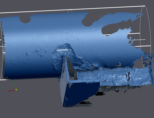
Figure 1 – Typical example of a Phased Array Scan Plan, illustrating weld coverage for each sectorial scan (either side of the weld) on a Single V, Butt Weld, 15mm WT.
 in Lieu of Radiography IPEC Inspection Engineers")
Figure 2 – Typical example/illustration of a “Lack of Penetration” when the weld is assessed using the Software package, after inspection. Views above include S-Scan & B-Scan.
 in Lieu of Radiography IPEC Inspection Engineers")
Figure 3 – Typical example/illustration of a “Toe Crack” when the weld is assessed using the Software package, after inspection. Views above include S-Scan & B-Scan.
Equipment used: Sonatest Phased Array / TOFD Flaw Detector, 32:128 & UT Studio+ Software Package
Benefits
- No health and safety implications with using ionising radiation
- Other work in vicinity does not need to be suspended during inspection
- Elimination of radiation protection measures
- Equal or higher reliability of examination in comparison to radiography
- High cost savings
- 100% coverage of weld
- Fast inspection carried out in real time
- Possible to characterise and size many defects & provides two dimensional sizing (lengths & depths)
- Weld assessment & analysis can be carried out directly after test, enabling contractors to clsoe area & proceed with further works
- Possible to produce both hardcopy & digital reports
Disadvantages
- Skilled operators with excellent background ultrasonic testing knowledge is a must
- Doesn‘t quite equal radiography in detection and characterisation of inclusions and gas pores
- Pipe wall thickness has to be >6.0mm for detection and characterisation of defects (> 6mm as per EN ISO 13588, however EN ISO 20601 allows 3.2mm to 8.0mm)
Conclusion
- PA/ToFD dramatically reduces health and safety implications
- PA/ToFD offers advantages in saving time and money
- Radiography offers benefits for detection of inclusions and porosity & also provides a radiograph for end user / clients.
- PA/ToFD can detect all defect types and characterise them in accordance with acceptance criteria.
- PA/ToFD can provide a digital data file of each weld or scan for the client, however it may be difficult to interpret if not trained.
Source/Credit: Norbert Trimborn (SGS), Sonatest
Author: James Murphy, Operations Manger of IPEC Inspection Ltd.