
Industrial Radiography (Radiographic Inspection) is a modality of non-destructive testing that uses ionizing radiation to inspect materials and components with the objective of locating and quantifying defects and degradation in material properties that would lead to the failure of engineering structures. It plays an important role in the science and technology needed to ensure product quality and reliability.
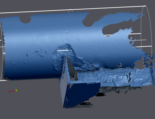
Industrial Radiography uses either X-rays, produced with X-ray generators, or gamma rays generated by the natural radioactivity of sealed radionuclide sources. After crossing the specimen, photons are captured by a detector, such as a silver halide film, a phosphor plate, flat panel detector or CdTe detector. The examination can be performed in static 2D (named radiography), in real time 2D, (fluoroscopy) or in 3D after image reconstruction (computed tomography or CT). Particular techniques such as X-ray fluorescence (XRF), X-ray diffractometry (XRD), and several other ones complete the range of tools that can be used in industrial radiography.
Inspection techniques can be portable or stationary. Industrial radiography is used in welding, casting parts or composite pieces inspection, aircraft maintenance, ballistics, turbine inspection, in surface characterisation, coating thickness measurement etc.

(Radiographic Image of a Welded Joint – Porosity within the body of the weld is easily identifiable)
X-Ray Generators
X-ray generators produce X-rays by applying a high voltage between the cathode and the anode of an X-ray tube and in heating the tube filament to start the electron emission. The electrons are then accelerated in the resulting electric potential and collide with the anode, which is usually made of Tungsten.
The X-ray that are emitted by this generator are directed towards the object to control. They cross it and are absorbed according to the object material’s attenuation coefficient. The attenuation coefficient is compiled from all the cross sections of the interactions that are happening in the material. The three most important inelastic interactions with X-rays at those energy levels are the photoelectric effect, compton scattering and pair production. After having crossed the object, the photons are captured by a detector, such as a silver halide film, a phosphor plate or flat panel detector. When an object is too thick, too dense, or its effective atomic number is too high, a linac can be used. They work in a similar way to produce X-rays, by electron collisions on a metal anode, the difference is that they use a much more complex method to accelerate them.
(Example below of a Rigaku Radioflex 300KV Directional X-Ray Generator)

Sealed Radioactive Sources
Radionuclides are often used in industrial radiography. They have the advantage that they do not need a supply of electricity to function, but it also means that they can’t be turned off. The two most common radionuclides used by IPEC Inspection Ltd. are Iridium-192 and Selenium-75.
- Ir-192: Industrial radiography
- Se-75: Industrial radiography
- Yb-169: Industrial radiography
- Co-60: Density and fill height level switches, industrial radiography
These isotopes emit radiation in a discrete set of energies, depending on the decay mechanism happening in the atomic nucleus. Each energies will have different intensities depending on the probability of a particular decay interaction. The most prominent energies in Cobalt-60 are 1.33 and 1.17 MeV, and 0.31, 0.47 and 0.60 MeV for Iridium-192. From a radiation safety point of view, this makes them more difficult to handle and manage. They always need to be enclosed in a shielded container and because they are still radioactive after their normal life cycle, their ownership often requires a license and they are usually tracked by a governmental body. If this is the case, their disposal must be done in accordance with the national policies. The radionuclides used in industrial radiography are chosen for their high specific activity. This high activity means that only a small sample is required to obtain a good radiation flux. However, higher activity often means higher dose in the case of an accidental exposure.
(Example below of a Sentinel 880 Series Gamma-Ray Source Projector)

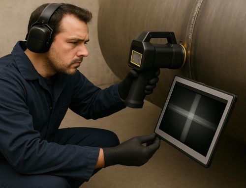
Inspection of products
Portable X-Ray generators or gamma radiation sources, most commonly Iridium-192 and Selenium-75, are used to inspect a variety of materials. The vast majority of radiography concerns the testing and grading of welds on pressurized piping, pressure vessels, high-capacity storage containers, pipelines, and some structural welds. Other tested materials include concrete (locating rebar or conduit), welder’s test coupons, machined parts, plate metal, or pipewall (locating anomalies due to corrosion or mechanical damage). Non-metal components such as ceramics used in the aerospace industries are also regularly tested. Theoretically, industrial radiographers could radiograph any solid, flat material (walls, ceilings, floors, square or rectangular containers) or any hollow cylindrical or spherical object.
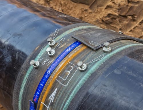
Inspection of welding
The beam of radiation must be directed to the middle of the section under examination and must be normal to the material surface at that point, except in special techniques where known defects are best revealed by a different alignment of the beam. The length of weld under examination for each exposure shall be such that the thickness of the material at the diagnostic extremities, measured in the direction of the incident beam, does not exceed the actual thickness at that point by more than 6%. The specimen to be inspected is placed between the source of radiation and the detecting device, usually the film in a light tight holder or cassette, and the radiation is allowed to penetrate the part for the required length of time to be adequately recorded.
The result is a two-dimensional projection of the part onto the film, producing a latent image of varying densities according to the amount of radiation reaching each area. It is known as a radio graph, as distinct from a photograph produced by light. Because film is cumulative in its response (the exposure increasing as it absorbs more radiation), relatively weak radiation can be detected by prolonging the exposure until the film can record an image that will be visible after development. The radiograph is examined as a negative, without printing as a positive as in photography. This is because, in printing, some of the detail is always lost and no useful purpose is served.
Before commencing a radiographic examination, it is always advisable to examine the component with one’s own eyes, to eliminate any possible external defects. If the surface of a weld is too irregular, it may be desirable to grind it to obtain a smooth finish, but this is likely to be limited to those cases in which the surface irregularities (which will be visible on the radio graph) may make detecting internal defects difficult.
After this visual examination, the operator will have a clear idea of the possibilities of access to the two faces of the weld, which is important both for the setting up of the equipment and for the choice of the most appropriate technique.
Defects such as delaminations and planar cracks are difficult to detect using radiography, particularly to the untrained eye.
Without overlooking the negatives of radiographic inspection, radiography does hold many significant benefits over ultrasonics, particularly insomuch that as a ‘picture’ is produced keeping a semi permanent record for the life cycle of the film, more accurate identification of the defect can be made, and by more interpreters. Very important as most construction standards permit some level of defect acceptance, depending on the type and size of the defect.
To the trained radiographer, subtle variations in visible film density provide the technician the ability to not only accurately locate a defect, but identify its type, size and location; an interpretation that can be physically reviewed and confirmed by others, possibly eliminating the need for expensive and unnecessary repairs.
For purposes of inspection, including weld inspection, there exist several exposure arrangements.
First, there is the panoramic, one of the four single-wall exposure/single-wall view (SWE/SWV) arrangements. This exposure is created when the radiographer places the source of radiation at the center of a sphere, cone, or cylinder (including tanks, vessels, and piping). Depending upon client requirements, the radiographer would then place film cassettes on the outside of the surface to be examined. This exposure arrangement is nearly ideal – when properly arranged and exposed, all portions of all exposed film will be of the same approximate density. It also has the advantage of taking less time than other arrangements since the source must only penetrate the total wall thickness (WT) once and must only travel the radius of the inspection item, not its full diameter. The major disadvantage of the panoramic is that it may be impractical to reach the center of the item (enclosed pipe) or the source may be too weak to perform in this arrangement (large vessels or tanks).
The second SWE/SWV arrangement is an interior placement of the source in an enclosed inspection item without having the source centered up. The source does not come in direct contact with the item, but is placed a distance away, depending on client requirements. The third is an exterior placement with similar characteristics. The fourth is reserved for flat objects, such as plate metal, and is also radiographed without the source coming in direct contact with the item. In each case, the radiographic film is located on the opposite side of the inspection item from the source. In all four cases, only one wall is exposed, and only one wall is viewed on the radiograph.
Of the other exposure arrangements, only the contact shot has the source located on the inspection item. This type of radiograph exposes both walls, but only resolves the image on the wall nearest the film. This exposure arrangement takes more time than a panoramic, as the source must first penetrate the WT twice and travel the entire outside diameter of the pipe or vessel to reach the film on the opposite side. This is a double wall exposure/single wall view DWE/SWV arrangement. Another is the superimposure (wherein the source is placed on one side of the item, not in direct contact with it, with the film on the opposite side). This arrangement is usually reserved for very small diameter piping or parts. The last DWE/SWV exposure arrangement is the elliptical, in which the source is offset from the plane of the inspection item (usually a weld in pipe) and the elliptical image of the weld furthest from the source is cast onto the film.
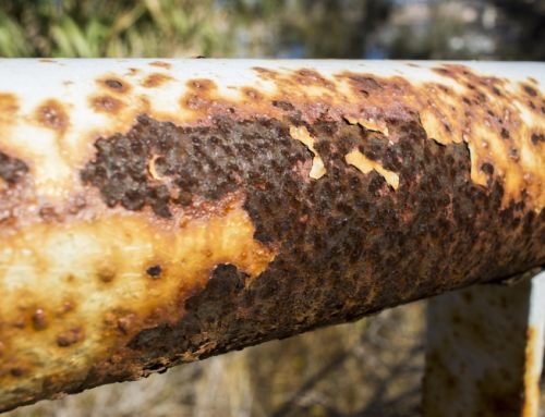
(Example below of Defective Welded Joints)


Safety
Radiation safety is a very important part of industrial radiography. Shielding can be used to protect the user of the harmful properties of ionizing radiation. The type of material used for shielding depends on the type of radiation being used. National radiation safety authorities usually regulate the design, commissioning, maintenance and inspection of Industrial Radiography installations. A collimator is a safety device which narrows a beam of particles or waves. To narrow can mean either to cause the directions of motion to become more aligned in a specific direction (i.e., make collimated light or parallel rays), or to cause the spatial cross section of the beam to become smaller (beam limiting device).
(Example below of a Collimator)

Source/Credit: Wikipedia/Industrial Radiography
Author: James Murphy, Operations Manger of IPEC Inspection Ltd.
Follow IPEC Inspection Ltd. on LinkedIn
Follow James Murphy on LinkedIn