
Inspection of Gas Pipelines
Without proper maintenance, the lifespan of gas pipelines can be greatly reduced, which can subsequently lead to people and the environment being exposed to potential hazards as well as costly infrastructure investments and network downtimes. In order to safeguard against any potential defects, corrosions and failure, asset owners and non destructive testing (NDT) service providers must carry out preventative integrity assessments during scheduled inspection intervals. Traditionally, pipeline inspections were inherently complex and challenging due to field conditions and safety considerations. Systematic monitoring requires skilled inspection technicians that were often difficult to find.
In addition, non destructive testing (NDT) on pipelines traditionally required manual measurement techniques using a ultrasonic thickness gauge, pit gauge, tracing paper, rulers & many other accessories. Such techniques were exceptionally time consuming, cumbersome and inevitably ramped up operational costs while limiting the pipelines ability to operate at full capacity. Further to this, many issues arose regarding the accuracy, reliability and repeatability of manual inspections in harsh pipeline environments. Characterising a pipeline’s material integrity means looking for signs of internal, external and atmospheric corrosion as well as mechanical damage, such as wrinkles, dents and gouges. The vast amounts of data collected could mislead technicians to either recommend overly conservative remedial actions, which impacted network availability, or assess that pipes were still fit for service when they were not.

How much experience is required?
The need for qualified & competent inspectors is growing annually as pipeline operators and owners expand their networks. In today’s market, finding pipeline inspectors with all the necessary training as well as the right know-how on a variety of different conventional measurement techniques and tools is extremely difficult. Training technicians to become certified pipeline inspectors can be a long and costly endeavour. Even after they are trained, technicians are not immune to human error or capturing poor data. Due to the harsh working conditions, turnover is extremely high. Solutions are therefore required to address these inspection staff issues.
Current Problems & Difficulties
Pipelines are inherently complex, so inspecting them for damage such as corrosion, weld arc strikes and atmosphere induced cracking, gouges & dents can be extremely time consuming. Traditional techniques, which have previously been manual, meant that the accuracy, reliability and repeatability were dependent on a technician’s skill and often compromised by the surrounding environment on any given inspection day.
These manual inspection techniques often require lengthy tool setups and measurement times that could span hours or even days, depending on the section of the pipe to be assessed. In addition, the complexity of the pipeline’s geometry & unstable excavation environment can hinder the inspection teams ability to spot some further important information or damage.
Once the data is collected, extra time is then needed to analyise & validate the measurements on-site before sending them to off-site engineers for further assessments.
For burst pressure calculations using manual techniques, the finer the grid, the more accurate the measurements. This means that a 2X smaller grid represents 4X more measurements (squared function). Multiple data points take time to measure, and when these data points need to be remeasured, the technician has to go back in the trench to correct any measurement errors.
This means that inspectors and integrity engineers may question the accuracy and availability of the data and therefore lack the confidence in providing their final recommendations.
So what’s the solution?
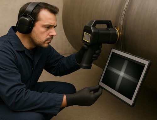
With handheld 3D scanners, pipeline operators, asset owners as well as NDT service providers can benefit from an easy-to-use, fast and effective tool for all types of pipeline integrity inspections. Handheld scanners such as our Creaform 3D, Go! Scan Spark offer a complete 3D picture (with geometry, texture, and colour) aswel as integrated “Pipecheck” software.
This makes it very convenient to acquire accurate measurement data on pipes up to 18m in length (in one scan) and directly at a pipeline’s specific inspection quadrant. The unique self-positioning and dynamic referencing capabilities of the Go! Scan Spark means anyone can perform a pipeline inspection. No previous metrology experience or extensive training on a series of different measurement techniques are required, only specific training on your applicable 3D scanner & software.
Using optical technology, 3D scanners generate highly accurate, repeatable and reliable results with exceptional resolution & speed, regardless of user ability. Using our Go! Scan 3D scanner, we are able to achieve up to 1,500,000 measurements per second, an accuracy of up to 0.05mm & with a resolution of 0.1mm.

How does the software integrate with the scanning?
Corrosion
Pipecheck has the capacity to measure both the internal corrosion (thanks to UT or interior 3D scanning if possible) and external corrosion (with 3D scanning) to get a complete 3D visualization of damage for more detailed, in-depth analyses. This allows high-resolution capture of all corroded areas & improved scanning performance for small features, such as pitting.
The software’s “Corrosion Analysis” function allows for many automated commands which drastically reduce technician workload such as;
- Feature detection using real pipe geometry,
- Automatically applied interaction rules,
- Estimated burst pressure calculations,
- Enhanced virtual pit gauge capabilities near welds and obstacles,
- ASME Compliant: B31.G, B31.G modified, Effective Area.
Denting (Mechanical Damage)
Pipecheck provides key pipeline inspection functionalities, such as the automatic detection of the maximum depth, which can be difficult to find with traditional measurement methods, like pit gauges & pipe calipers.
The software’s “Dent Analysis” function allows for many automated commands which drastically reduce technician workload such as;
- Automatic maximum depth detection,
- Depth measurement using straight edge and pipe calipers,
- Strain-based analysis,
- Shoulder section available,
- ASME Compliant: B31.8R, Strain Analysis.
Wrinkle Analysis
The wrinkle analysis module is programmed to calculate the crest-to-trough depth of the ripple as well as the wavelength, circumferential extent, and diameter restriction enhancing the quality of pipeline inspection analyses and reporting. This allows for fast and independent 360° measurements and the ability to scan multiple wrinkles simultaneously during a single acquisition.
The software’s “Wrinkle Analysis” function allows for many automated commands which drastically reduce technician workload such as;
- Crest-to-trough depth of deformations,
- Wavelength,
- Circumferential extent,
- Diameter restriction.

So what’s the end result?
Step 1: Initial Inspection
See example below of a 24″ Pipe & Isolation Joint, Material: API 5L X52 located in an “above ground installation” (AGI).

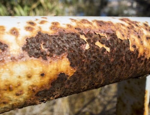
An initial visual inspection highlighted multiple areas of corrosion under the pipe supports which is evident in the photo above & below. Corrosion under supports (CUS), as its name suggests, is corrosion that occurs at the interface between a metal component and the object that supports it. Support locations such as brackets and clamps, tend to act as entrapment areas for water and other liquids that can result in corrosion. This type of corrosion is highly localised and can result in the formation of pits and other forms of corrosion damage.

Photo 1 – LHS Pipe Support, No. 1
Step 2: Cleaning & Shot Blasting of Pipe
Once the initial inspection was concluded, it was decided that the corrosion would require a more thorough investigation using a 3D scanner. Shot blasting was required to prepare the surface for scanning with the added benefit of removing all grease, rust & scale.
Shot Blasting is a form of abrasive cleaning which is primarily used for surface protection and preparation of a part, such as a pipeline, prior to applying a paint or a coating. The process involves propelling abrasive materials at the surface of the metal part at extremely high pressure. The shot blasting cleans, strengthens and polishes the metal. It also allows any weaknesses to be identified and rectified by the asset owner or NDT service provider before applying any coating.
See image below of the 24″ Pipe & Isolation Joint, after shot blasting & ready for 3D Scanning.

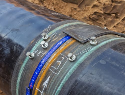
Step 3: Conducting the 3D Scan
Scanning in “Pipecheck” is separated into two main operating principles; Target Acquisition & Surface Acquisition.
The Target Acquisition is the most important step in regards to accuracy. The white targets (as pictured above) allow the scanner to know where it is at all times and is therefore crucial to the accuracy of the scan.
The Surface Acquisition is done using the lasers. The lasers are deformed by the surface and the cameras record that deformation to create the surface.
The Pipecheck arrow (reference arrow) allows the scan to be properly aligned and can be used to align the pipe to other types of data such as ILI and UT. It is usually placed at the 12 O’ Clock position, close to a girth weld in order to properly reference it. It should be placed parallel to the pipe axis.
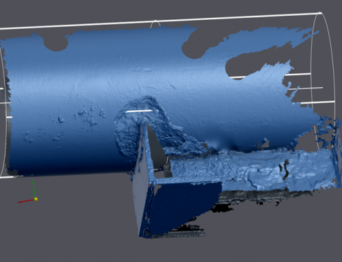
Once the scanning is complete, you should end up with something similar to below;

12 O’ Clock Position

3 O’ Clock Position

6 O’ Clock Position

9 O’ Clock Position
Step 4: Analysing the Data
Code Selection
You can select between ASME B31G or for Depth Analysis Only.
Sflow Parameters
The flow stress is used in the B31G, Modified B31G and Effective Area standard to calculate the bursting pressure.
The inspection & Sflow parameters will be later displayed in the report, so it’s vitally important to select the correct specifications from the beginning. The Design Factor, Specified Min. Yield Strength (SMYS) & Pipe Material Grade are the most important values & should be provided from the pipeline / asset owner prior to any analysis being carried out.
Pressure Parameters
The MAOP (Max. Allowable Operating Pressure) is the main pressure parameter to which the burst pressure is compared. This is automatically calculated by the software according to “Barlows Equation”. The MOP (Max. Operating Pressure) is also an important value that should be provided to the inspection team by the asset owner.
Interaction Parameters
During the analysis process, corroded areas are identified and listed as corrosion features. Their shapes and size will vary depending of the interaction parameters.
Critical factor (%) = Depth (% of wall thickness) at which a corrosion pit is deep enough to be evaluated and listed.
Threshold for corroded area (%) = Depth (% of wall thickness) at which the corrosion feature dimensions are measured and interaction rules are applied.
Axial criteria = Minimal axial distance between 2 corroded areas for which they will remain separated features. Length or thickness multiplier can be used as units for this interaction criteria.
Circumferential criteria = Minimal circumferential distance between 2 corroded areas for which they will remain separated features. Length or thickness multiplier can be used as units for this interaction criteria.
Axial & Circumferential Criteria
Surrounding corroded areas may be grouped into a single feature (cluster) according to the following interaction rules;
- Each corroded area is delimited according to the selected Interaction method, at the depth defined by the Threshold for corroded area.
- Delimited areas are enlarger by ½ x Axial and Circumferential criterion (red lines).
- If 2 enlarged areas overlap each other, they are grouped together. If there is no overlap between 2 enlarged areas, it means the corroded areas have a distance between each other at least equal to 1 x the axial and circumferential criteria.
Critical factor and Threshold
The critical factor is used to identify corrosion features;
- A virtual pit-gauge depth measurement is taken in every grid (pixel) based on the scan resolution set.
- Every group of pixels deeper than the critical factor is identified as a single anomaly (called feature).
- The feature dimensions start and end at the threshold depth value.
- Anomalies are combined into clusters based on the interaction rules.
- The threshold value must be equal or smaller than the critical factor value. If no threshold value is entered, the feature dimensions and the interaction criteria are measured at the critical factor.
Step 5: Results
2D Image of the scanned pipe featuring the deepest pit (Identification: Feature No. 15)
Maximum Depth of 2.68mm, Effective Area RPR (MOP): 2.78, RPR (MAOP): 2.30, Axial Length: 197.02mm.
Calculated Safe Pressure: 84.77 Bar
Total Volume of Material Loss: 977.32mm2

The pipecheck software can also illustrate a defects circumferential positioning, circumferential width, anomaly class, axial position, effectives areas etc. etc.
3D Image of the scanned pipe featuring the deepest pit (Identification: Feature No. 15)

All this data is then extracted into an excel spreadsheet & a report is created for the client.
See below examples of the data we extract from the software and make available to our clients for reporting & filing purposes.


As can be seen above, the data and analysis functions available to the pipeline enginners & asset owners are now endless. These are some of the extra benefits of using the “Pipecheck” software when compared with Manual techniques;
The software’s “Corrosion Report” function allows for;
- Excel report including worst-case profiles and predicted failure paths,
- Export to CSV available for further analysis,
- Mesh export available,
- Customizable pass/fail criteria,
- Snapshot tool for 3D reporting.
The software’s “Dent Report” function allows for;
- Cross-section details (axial and circumferential),
- CSV depth grid export,
- Mesh export available,
- Excel report with ovality measurements (diameter with calipers).
The software’s “Wrinkle Report” function allows for;
- Excel report with all standard information for wrinkle analysis.
Author: James Murphy, Operations Manger of IPEC Inspection Ltd.
Follow IPEC Inspection Ltd. on LinkedIn
Follow James Murphy on LinkedIn
Check out the following link where Creaform 3D mentions us & what we do.
https://www.creaform3d.com/IPEC Inspection Article
Source/Credit: Creaform3d.com/en/applications, Creaform NDT