A boroscope is an optical instrument used in industrial applications to view the interior of technical hollow bodies or interior surfaces in tubes, pipes, holes, gas turbine engines or other hard-to-reach places while the term “endoscope” is normally used in the medical field. The optical system in some instances is accompanied by (typically fiber-optic) illumination to enhance brightness and contrast. An internal image of the illuminated object is formed by the objective lens and magnified by the eyepiece which presents it to the viewer’s eye. Boroscopes can be grouped into two main categories, namely “Rigid Borescopes” and “Flexible Boroscopes”
Rigid Boroscopes
The rigid borescopes are characterized by a rigid shaft. The image and light transmission often takes place by means of a rod lens system. Some borescopes may also be used in high-temperature temperatures which are additionally equipped with a cooling jacket as they are used at temperatures of up to 2000°C. Rigid boroscopes are normally used for drill holes and openings with straight access according to their design.
The rigid borescopes can also sometimes be compared to a periscope, where the objective is placed quite near the object or detail to be examined, while the ocular is placed at the desired distance from the objective. The objective and the ocular are connected by means of one or more removable extension tubes. The borescope length can thus be varied as required. The image is transferred from the objective to the ocular by means of an optical system which is built into the tube.
The illumination of the surface to be observed is achieved by means of a 6-15 V halogen lamp which is contained in the objective lube. The light may also be transferred by means of a bundle of optical fibers which thus serve as a light guide. The light guide surrounds the lens system itself and is in principle equivalent to trust of the fiberscopes.
Flexible Boroscopes
Flexible borescopes have a movable, flexible shaft which can bend around various elbows, valves & other hard-to-reach places. In contrast to rigid borescopes, flexible borescopes transmit images through structured, flexible fiber bundles, also known as image bundles. Image bundles consist of individual fibers joined together with each fiber transmitting one pixel from the objective to the ocular.
Some boroscopes can even contain up to 120,000 fibers, each consisting of two layers of glass, with one “core” of glass surrounded by an outer layer of glass of differing refractive index. When the light strikes the interface between the core material and the outer layer, a nearly perfect internal reflection occurs. In this way the light is guided through each individual fiber. The flexibility and mobility of the probe is guaranteed by the image bundle system and the plastic coating. Due to the technical design, the flexible borescopes can be manufactured in smaller working diameters than rigid borescopes.
Boroscopes can be supplied with distance adjustments just like an ordinary camera, so that the image can be focused sharply at any distance from a few millimetres up to infinity. When adjusting to very small distances the image is magnified, so that even very small details can be inspected.
The flexible boroscope can normally be supplied in diameters ranging from about 2.0mm to 13.5 mm and in lengths from about 300mm to 7m.
Video Boroscopes
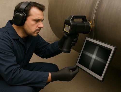
The video boroscope represents a further development in technology from what was discussed previous. Video boroscope equipment operates on the principle that a small electronic sensor detects the image and transmits the signals recorded to a video processor from which the signal is sent to a monitor. In addition to providing a large, sharp colour image, the equipment is capable of automatically focusing. It is also possible to add text in the image field, e.g. to indicate the location of the examination, the object, to freeze the image so that details can be studied, and more.

(Example of a video boroscope being used on a gas turbine engine)
Orbital Welding
Orbital welding is a specialized area of welding whereby the arc is rotated mechanically through 360° (180 degrees in double up welding) around a static workpiece, an object such as a pipe, in a continuous process. The process was developed to address the issue of operator error in gas tungsten arc welding processes (GTAW), to support uniform welding around a pipe that would be significantly more difficult using a manual welding process, and to ensure high quality repeatable welds that would meet more stringent weld criteria set by ASME. In orbital welding, computer-controlled process runs with little intervention from the operator.
It is very difficult to achieve the highest standards of quality required in the biopharmaceutical industry when using standardised manual welding. This is due to certain awkward welding positions, (overhead and down-hand welds for example) which can sometimes lead to defective welds due to restricted access etc. In order to have complete control over the weld pool, a perfect balance must be maintained between gravitational force and surface tension at every position of the torch. By using mechanised variants of the technique, certain parts of the welding process are handled by mechanical components. In an ideal situation, all welding parameters would be fully programmed before welding is started. In practice, however, the presence of variable constraints means that it is often necessary for the welder to make corrective interventions.
A successful automatic orbital GTA weld is 100% repeatable as long as the operator monitors variables and performs periodic samples or coupons which are inspected for complete penetration. Noticing that a variable has changed is a primary skill and can be easily missed. Training and experience are required for an operator to be successful at consistently producing acceptable welds.
The successful automatic orbital GTA weld is very dependent upon refinement of several critical variables that involve programming the welding machine and set-up of the “weld head”. Maintenance of the weld head often becomes a factor in repeatability of successful welds as weld head internals can become charred from improper use.
Successful orbital welding is also dependent upon using high quality tubing material. Typically only 316L stainless steel tubing (not pipe) and fittings are used for automatic orbital GTA welding and are obtained from a number of specialty manufacturers. The weld quality depends upon having a reasonably clean source of Argon for backing and shielding gas. Minimum purity would be 99.995% for typical industrial applications. For some applications it is necessary to use ultra high purity argon, 99.9998% purity and such applications requires the use of all high purity purge equipment (valves, regulators and flow control). Typically, no rubber components can be used for purge gas apparatus since the rubber absorbs and releases moisture and oxygen into the argon stream. Moisture and oxygen (in Argon) are contaminants detrimental to a successful automatic orbital weld.
On site, weld coupons are typically prepared at the beginning of a welding shift or any time a welding variable is adjusted or changed. Each coupon should be examined internally and externally to verify full penetration, proper bead width and other criteria. With smaller diameter pipe or tubing, it is usually necessary to section open the coupon to examine the weld bead. All coupons should exhibit complete penetration and consistent bead width. Variations in consistency are an indicator of a problem that must be resolved before continuing.
Orbital welding is more commonly performed on tubing than on pipe for several reasons, most important being that the production of tubing yields very consistent outside diameters which is critical to proper fit up in the weld head. Automatic Orbital GTA welding has become the standard joining method for high integrity gas and liquid systems used in the Semiconductor and Pharmaceutical manufacturing industries. These systems are rated for extreme purity and leak tight integrity. An entire specialty industry supplying valves, fittings, regulators, gauges and other components for orbital welding and use in high purity applications has developed since the mid 1980s. For tube welding in high purity applications, only a fully enclosed weld head may often be specified.

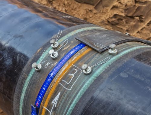
(Example of an Automatic Orbital GTAW Weld)


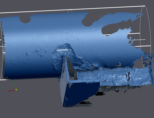
(Example of an Automatic Orbital GTAW Weld using a Video Boroscope)
Where can I use a Video Boroscope?
- Internal Weld Inspections
- Aviation Inspections
- Pharmaceutical Systems (Quality Control of Orbital Welds)
- Pharmaceutical Plant Operations, e.g. WFI or CIP Pipe Inspections
- HVAC Examinations
- Small Vessel Inspections
- Maintenance Examinations of Critical Components
- Wind Turbine Gearbox Inspections
- Power Generation Asset Inspections
Page 1: Visual Inspection
Page 2: Visual Boroscope Inspection
Source/Credit: Wikipedia_Boroscope Inspection
Author: James Murphy, Operations Manger of IPEC Inspection Ltd.