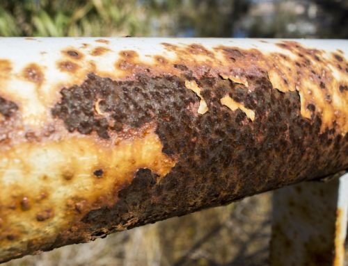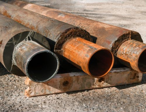

Ultrasonic Testing (UT) is within the family of non-destructive testing techniques based on the propagation of ultrasonic waves in the object or material tested. In most common UT applications, very short ultrasonic pulse-waves with center frequencies ranging from 1 – 15 MHz, and occasionally up to 50 MHz, are transmitted into materials to detect internal flaws or to characterize materials. A common example is ultrasonic thickness measurement, which tests the thickness of the test object, for example, to monitor pipework corrosion.
Ultrasonic testing is often performed on steel and other metals and alloys, though it can also be used on concrete, wood and composites, albeit with less resolution. It is used in many industries including steel and aluminium construction, metallurgy, manufacturing, aerospace, automotive and other transportation sectors.
In ultrasonic testing, an ultrasound transducer connected to a diagnostic machine is passed over the object being inspected. The transducer is typically separated from the test object by a couplant (such as oil) or by water, as in immersion testing. However, when ultrasonic testing is conducted with an Electromagnetic Acoustic Transducer (EMAT) the use of couplant is not required.
There are two methods of receiving the ultrasound waveform: reflection and attenuation. In reflection (or pulse-echo) mode, the transducer performs both the sending and the receiving of the pulsed waves as the “sound” is reflected back to the device. Reflected ultrasound comes from an interface, such as the back wall of the object or from an imperfection within the object. The diagnostic machine displays these results in the form of a signal with an amplitude representing the intensity of the reflection and the distance, representing the arrival time of the reflection. In attenuation (or through-transmission) mode, a transmitter sends ultrasound through one surface, and a separate receiver detects the amount that has reached it on another surface after traveling through the medium. Imperfections or other conditions in the space between the transmitter and receiver reduce the amount of sound transmitted, thus revealing their presence. Using the couplant increases the efficiency of the process by reducing the losses in the ultrasonic wave energy due to separation between the surfaces.
(Example below of a Sonatest Wave Ultrasonic Flaw Detector and it’s interactive scan plan)

Compression Probe Inspection (Longitudinal Wave)
Pulse-echo ultrasonic measurements can determine the location of a discontinuity in a part or structure by accurately measuring the time required for a short ultrasonic pulse generated by a transducer to travel through a thickness of material, reflect from the back or the surface of a discontinuity, and be returned to the transducer. In most applications, this time interval is a few microseconds or less. The two-way transit time measured is divided by two to account for the down-and-back travel path and multiplied by the velocity of sound in the test material.
The result is expressed in the well-known relationship; d= vt/2 where d is the distance from the surface to the discontinuity in the test piece, v is the velocity of sound waves in the material, and t is the measured round-trip transit time.
Image 1 & Image 2 below represent the A-Scan data you would likely see on an Ultrasonic flaw detector as you move a longitudinal wave transducer over the surface of a stainless steel test block. The return echoes on the right of the stainless steel block illustrate the different responses you would expect to see when the transducer passes over a defect within the test block.

(UT Image No. 1)

(UT Image No. 2)
Precision ultrasonic thickness gages usually operate at frequencies between 500 kHz and 100 MHz, by means of piezoelectric transducers that generate bursts of sound waves when excited by electrical pulses. A wide variety of transducers with various acoustic characteristics have been developed to meet the needs of industrial applications. Typically, lower frequencies are used to optimize penetration when measuring thick, highly attenuating or highly scattering materials, while higher frequencies will be recommended to optimize resolution in thinner, non-attenuating, non-scattering materials.
In thickness gauging, ultrasonic techniques permit quick and reliable measurement of thickness without requiring access to both sides of a part. Accuracy’s as high as ±1 micron or ±0.0001 inch can be achieved in some applications. It is possible to measure most engineering materials ultrasonically, including metals, plastic, ceramics, composites, epoxies, and glass as well as liquid levels and the thickness of certain biological specimens. On-line or in-process measurement of extruded plastics or rolled metal often is possible, as is measurements of single layers or coatings in multilayer materials. Modern handheld gages are simple to use and very reliable.
Angle Probe Inspection (Shear Wave)
Often straight beam testing will not find a defect. For example, if the defect is vertical and thin enough, it will not reflect enough sound back to the transducer to let the tester know that it exists. In cases like this, another method of ultrasound testing must be used. The other method of ultrasound testing is angle beam testing. Angle beam testing uses an incidence of other than 90 degrees. In contact testing, an angled plastic block is place between the transducer and the object to create the desired angle. For angle beam testing in immersion systems, a plastic block is not needed because the transducer can simply be angled in the water.
If the angle of incidence is changed to be anything other than 90 degrees, longitudinal waves and a second type of sound wave are produced. These other waves are called shear waves. Because the wave entered at an angle, it does not all travel directly through the material. Molecules in the test object are attracted to each other because solids have strong molecular bonds. The molecules carrying the sound are attracted to their surrounding molecules. Because of the angle, those sound carrying molecules get pulled by attracting forces in a direction perpendicular to the direction of the wave. This produces shear waves, or waves whose molecules travel perpendicular to the direction of the wave.

(UT Image No. 3)
Angle beam testing and a change in the angle of incidence also creates further complications. Remember that when a wave hits a surface at an angle, it will be refracted, or bent, when it enters the new medium. Thus, the shear waves and the longitudinal waves will be refracted in the test object. The amount of refraction depends on the speed of sound in the two mediums between which the wave is traveling. Since the speed of shear waves is slower than the speed of longitudinal waves, their angles of refraction will be different. By using Snell’s law, we can calculate the angle of refraction if we know the speed of sound in our material.
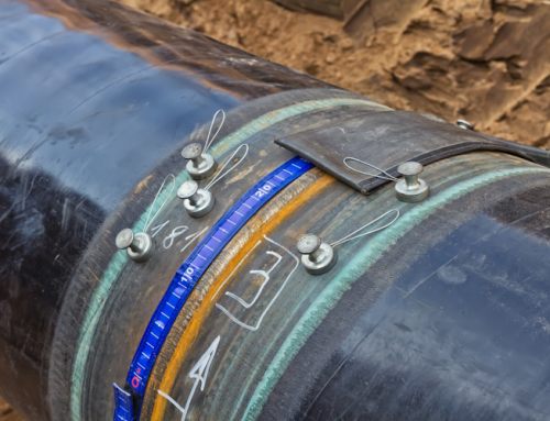
Welded Joints
The most commonly occurring defects in welded joints are porosity, slag inclusions, lack of side-wall fusion, lack of inter-run fusion, lack of root penetration, undercutting, and longitudinal or transverse cracks. With the exception of single gas pores all the defects listed are usually well detectable by ultrasonics. Most applications are on low-alloy construction quality steels, however, welds in aluminum can also be tested. Ultrasonic flaw detection has long been the preferred method for non-destructive testing in welding applications. This safe, accurate, and simple technique has pushed ultrasonics to the forefront of inspection technology.
Ultrasonic weld inspections are typically performed using a straight beam transducer in conjunction with an angle beam transducer and wedge. A straight beam transducer, producing a longitudinal wave at normal incidence into the test piece, is first used to locate any laminations in or near the heat-affected zone. This is important because an angle beam transducer may not be able to provide a return signal from a laminar flaw.
(Example below of a Sonatest Wave Ultrasonic Flaw Detector illustrating a defect within the body of the weld)

The second step in the inspection involves using an angle beam transducer to inspect the actual weld. Angle beam transducers use the principles of refraction and mode conversion to produce refracted shear or longitudinal waves in the test material. [Note: Many AWS inspections are performed using refracted shear waves. However, material having a large grain structure, such as stainless steel may require refracted longitudinal waves for successful inspections.] This inspection may include the root, sidewall, crown, and heat-affected zones of a weld. The process involves scanning the surface of the material around the weldment with the transducer. This refracted sound wave will bounce off a reflector (discontinuity) in the path of the sound beam. With proper angle beam techniques, echoes returned from the weld zone may allow the operator to determine the location and type of discontinuity.
To determine the proper scanning area for the weld, the inspector must first calculate the location of the sound beam in the test material. Using the refracted angle, beam index point and material thickness, the V-path and skip distance of the sound beam is found. Once they have been calculated, the inspector can identify the transducer locations on the surface of the material corresponding to the crown, sidewall, and root of the weld.
Advantages of Ultrasonic Inspection
- High penetrating power, which allows the detection of flaws deep in the part.
- High sensitivity, permitting the detection of extremely small flaws.
- In many cases only one surface needs to be accessible.
- Greater accuracy than other nondestructive methods in determining the depth of internal flaws and the thickness of parts with parallel surfaces.
- Some capability of estimating the size, orientation, shape and nature of defects.
- Some capability of estimating the structure of alloys of components with different acoustic properties
- Non-hazardous to operations or to nearby personnel and has no effect on equipment and materials in the vicinity.
- Capable of portable or highly automated operation.
- Results are immediate. Hence on the spot decisions can be made.
Disadvantages of Ultrasonic Inspection
- Manual operation requires careful attention by experienced technicians. The transducers alert to both normal structure of some materials, tolerable anomalies of other specimens and to faults therein severe enough to compromise specimen integrity. These signals must be distinguished by a skilled technician, possibly requiring follow up with other non-destructive testing methods.
- Extensive technical knowledge is required for the development of inspection procedures.
- Parts that are rough, irregular in shape, very small or thin, or not homogeneous are difficult to inspect.
- Surface must be prepared by cleaning and removing loose scale, paint, etc., although paint that is properly bonded to a surface need not be removed.
- Couplants are needed to provide effective transfer of ultrasonic wave energy between transducers and parts being inspected unless a non-contact technique is used. Non-contact techniques include Laser and Electro Magnetic Acoustic Transducers (EMAT).
- Equipment can be expensive.
Source/Credit: Wikipedia/Ultrasonic Inspection & nde-ed.org/ultrasonics
Author: James Murphy, Operations Manger of IPEC Inspection Ltd.